Add surface gripper
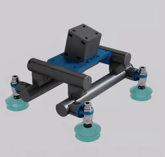
Configure a surface gripper in a scene. This guide demonstrates the workflow using a quad suction gripper. Video steps illustrate the process.
Additional information regarding the surface gripper properties can be found in the Isaac Sim documentation .
Add surface gripper object
The following instructions refer to the surface gripper object that was introduced with Isaac Sim 5.0.
- Drag and drop the tool via the
Contentbrowser into the scene. - Add the surface gripper object from the menu
Create→Isaac→Robotsto the tool’s Xform.
Create action graph
- Create an action graph via the menu
Create→Visual Scripting→Action Graph. - Add a surface gripper node from the menu.
- In the surface gripper node’s
Inputproperties, provide the previously created surface gripper object as the surface gripper parameter.
Once you have tested the surface gripper successfully, you can then connect an On IO Change node with the surface gripper node. For further details refer to Robot controller IOs.
Create D6 joint
- Create a D6 joint via the menu
Create→Physics→Joint→D6 Jointinside the scope of one of the tool’s Xforms. - Via the menu
Add→Edit API Schema, add theIsaacAttachmentPointAPIto the joint. - The joint must have
Exclude from Articulationset totruein its properties panel. - Set the local position and rotation of the joint coordinate with respect to
Body 0andBody 1.
Any prim with rigid body properties can be selected. This defines the contact point for where the workpiece is gripped. See what happens if you don’t define Body 1 in the troubleshooting section.- Switch between the local and world coordinate system display using the toolbar.
- Rotate the coordinate frame so the z-axis points downwards in the direction where the workpiece will be located. The initial rotation of the joint in the video is already pointing downwards.
- In the properties panel, scroll to the
Raw USD Propertiesand define theForward AxistoZ.
If needed, the clearance offset can also be specified.
The clearance offset defines the beginning of the measurement range for the ray casting that checks whether an object is ready to pick. - Repeat steps 1-5 for all suction cups of the gripper.
Configure surface gripper
- Configure the
Surface Gripperproperties. Some example parameters are provided in the explanatory video and the table.- The force limits must be adapted to the physical gripper’s properties.
- The surface gripper works by sending a raycast from the joint world position in the direction of the forward axis.
- The max grip distance specifies the length of the ray. For detailed information, refer to the surface gripper documentation from NVIDIA.
- Select all created D6 joints as
Attachment Points.
| Parameter | Value |
|---|---|
| Retry Interval | 0.0 |
| Max Grip Distance | 0.05 |
| Coaxial Force Limit | 1000.0 |
| Shear Force Limit | 1000.0 |
Test surface gripper
Test the created surface gripper by using the Close button in the SurfaceGripper object’s property panel.
Troubleshooting
Prevent snapping of the tool when moving it
If there is no other suitable prim with rigid body properties available and you thus assign only one body for the D6 joint in the surface gripper, Isaac Sim automatically assigns the second body to world. What’s happening then is:
- Without specifying the location of the D6 joint with respect to Body 1, the tool is translated.
- The position and rotation with respect to world prim remain fixed. This causes the D6 joint to snap together on simulation start, breaking the tool.
Define Body 1
Every prim that has rigid properties and a fixed spatial relationship to the D6 joint can serve as the Body 1 prim in the D6 joint property panel. E.g., if the tool is connected to a robot model, this could be the robot’s flange prim.
The video illustrates this by using a plane mesh with rigid properties to mimic a robot flange. The plane prim is then connected to the tool via a fixed joint.
As soon as Body 1 is defined, the tool can be moved around without destroying the D6 joint.